 This Site is slowly but continuously improved :-)
SMAGS
SMAGS, the Sunken Mill Adaptable Grating Spectrograph is, by optical design, a classical grating spectrograph.
The "adaptable" refers to the fact that several components may be quickly adjusted or exchanged:
- rotatable slit plate with various apertures
- exchangable camera lenses, with variable focus
default a 80mm/F1.8 CZJ Pancolar and 100mm/F2 and 135mm/F2.8 Olympus lensses - exchangable gratings; all gratings can be rotated in all 3 axes for finetuning
default 600 lines/mm blazed for 500 nm and 1200 lines/mm blazed for 750 nm - guiding on reflective slit, or [for faint objects] option for off-axis guiding on another star in the telescope field of view
The default configurations are:
- 600 l/mm grating + 80mm camera, which covers the spectral range between (and including) H-gamma and H-alpha, 420-680 nm at 0.45 to 0.8 nm resolution depending on slit width; 0.45 nm resolution for 50 micron slit (4.4 arcsec slit on the C9)
- 1200 l/mm grating + 80mm camera, which covers the range around H-alpha, 535-670 nm at 0,20 nm resolution (3.5 arcsec slit on C9)
- (currently unused:) 1200 l/mm grating + 135mm camera, which covers the range around H-alpha, 585-670 nm at 0,16 nm resolution (3 arcsec slit on C9)
A switch to another slit takes less than an hour. A switch to another grating takes me currently a few hours, which is mainly due to getting a good alignment of the slit/grating position with the CCD rows - this needs subtle rotation by hand and subsequent measurements to check the alignment.
Update: since the end of 2015 I replaced the 600 l/mm reflection grating by a mirror + 600 l/mm VPH (volume phase holographic) transmission grating. This has greatly improved the transmission of the instrument. However, the VPH grating is difficult to align and a change of gratings would be a major effort.
SMAGS components & construction
The spectrograph consists of more than 50 parts, and due to my limited time took more than a year to be finished. In the following, the main units are described.
Spectrometer Box
The mechanical design of the box containing the optics is similar to the one first employed for the prism spectrograph, that was later adapted to the SMEtte prototype.
The box is a "double sandwich". The base plate consists of 15mm ALUCORE aluminium honeycomb sandwich, which is light yet very stiff.
This baseplate serves as optical bench, on which the optics are mounted. The top plate is 6mm Alubond, a sandwich of Aluminium with a polymer in-between.
I would have prefered ALUCORE here too, but have not been able to obtain a piece of the required size (the minimum wholesale size is 2.5 x 1.25 meter and very expensive).
The Alubond plate is heavier than the base plate and less stiff, but still half the weight of solid Aluminium of the same stiffness.
Top and bottom are separated by 3 spacers. Thin aluminium plates (1mm thick) or lids (for easy access) close the spectrograph at the sides.
These side walls do not take any loads, since that is carried off by the spacers.

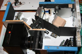
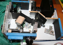
The baseplate of the spectrograph, with the front plate and two of three spacers attached (blue), as well as some of the thin side plates. The drawing on the plate indicates the optical path: light enters from lower left; the camera will be at upper right (click image to enlarge).
The front plate, which attaches to the telescope, is again 15mm ALUCORE.
This is the part of the spectroscope that takes most of the mechanical stress.
It fixates the base plate and the top plate against each other, and it has to hold the weight and torque of the spectrograph at the connection point to the telescope.
The main drawback of ALUCORE (apart from availability) is that it cannot be screwed from the sides (there's just flimsy honeycomb there).
The connection to base plate and top is done via beechwood blocks, which are epoxied to base and top on the outside of the spectrograph (not unlike the buttresses in medieval cathredral architecture :-) ).
The front plate is firmly pressed against these blocks using 8 M5 screws (any deformation that might occur in these blocks is harmless because it will at most change the position of the star on the slit, but slit and all optical elements are attached to the base plate and do not move against each other).
The spacers between top and bottom plate are made of wood. This may not be ideal from a stability point of view, but has the advantage that it is lightweight and can easily be screwed at the sides.
As with the wooden blocks on the front plate, any deformation in the spacers does not influence the optical bench.
Two spacers are near the front plate, one is at the back end, forming a stable triangle.
One of the spacers carries a flip mirror to view the telescope field of view, plus the slit viewing camera.
The weight of the empty spectrometer box is 2.85 kg, its size is 430x320x111 mm.
Front Optics
The "front optics" consist of:
- a flip mirror to position the star on the slit
- a slit viewing mirror and camera lens; the slit image may either be viewed by an eyepiece, or by a guiding camera
- optics for off-axis guiding

The flip mirror. This is a 3mm thick, 75mm diameter mirror from Surplus Shed. The flip mirror is fixed to the blue wooden side plate that also gives support to the 2" eyepiece and the guiding camera. Friction is applied by pressing a nylon scew to the rotation axis. This screw can be accessed via a hole in the spectrometer's top plate, without the need to open the box.
The off-axis guiding unit is in fact the part that cost me most headaches, and I do not even know if it is worth the trouble. The idea is to get for faint objects a guiding star, when the object to measure is to faint to use its light outside the slit edges. Other spectrograph designs, such as LISA or ALPY (see here) assume that there are always other faint objects in the field of view and usually that is the case.
The off-axis unit consists of one mirror that reflects the field of view above the slit to a second mirror, which bends the lightpath by 90 degrees through the base plate. On the base plate there is a large collimator lens (50 mm diameter), and at the outside is the smaller camera lens and the flange for the guiding camera.
The issue with off-axis guiding is that one either needs movable mirrors inside the spectrograph (difficult to control from outside, and movable also implies there may be a danger of tiny displacements during the exposure) or a movable camera (because the CCD chip is much smaller than the field of view).
I rejected the idea of using movable mirrors. This has as consequence that I need a movable camera and an independently moving camera lens (the smaller camera lens must be moved over the large collimator bean to get the full illuminated beam, and the camera must move against the camera lens to get the correct position in the field of view of the camera lens). At the moment of writing I have still issues with coma in the off-axis optics and the off-axis guiding hasn't been used yet.
Slit block
The initial design used the LHIRES III reflecting slit plate from Shelyak Instruments [link] This was mounted on an aluminium plate which could be rotated against another aluminium plate that was attached to the back of the slit block (made of 15mm plywood).
This rotation enables an adjustment to get the spectral lines nicely perpendicular to the dispersion direction.
On the front top of the slit block is the mirror for off-axis guiding. To get acces to the slit plate, this mirror could be flipped away (a feature that in the new design still exists, but is
obsolete since all access is now from the back).
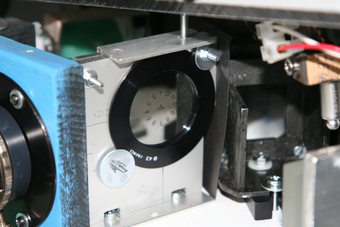
The new design uses as reflective slit the OVIO slit plate from Ken Harrison (see figure). The wooden slit block was replaced by a 6mm alubond sheet. The slit plate is glued to a mounting ring that is pressed with screws against the back of the slit block. By loosening the screws it can rotate on 2 support nipples.
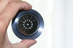
The OVIO slit plate, glued in its mounting (a 43mm COKIN filter adapter ring) using Pattex Extreme Repair.
There are 9 slits from 20 to 100 micron, as well as 3 pinholes from 20 to 100 micron.
Spectrometer Optics
The camera is a normal DSRL lens. This has the great advantage that it may be cheaply obtained as second-hand, that it has a good colour correction, and last but not least that it is easily focusable.
On the downside, the focussing changes its length. That implies that either the camera/lens assembly must be movable, or that the wall of the spectrograph must be movable.
I went for the latter option. Some light may leak around the lens where it protrudes inside the spectrometer, but a labyrinth effectively shields light from directly entering the spectrograph. It works well at night, but at daytime there is a noticeable amount of straylight.

The collimator under alignment. The collimator is a 200mm achromat from Thor Labs. Collimation is done by pointing a laser on a target. First the target is set without the collimator, such that the light beam will later be centered on the grating. Then the collimator lens is inserted and adjusted until the laser beam is again on the target. If the lens is kept perpendicular to the lightbeam, this ensures that the lens will be centered.
Gratings
I use 30x30mm gratings from Edmund Scientific. On the back of the grating, a ring is glued with 25mm diameter. Usually I glue mirrors with a drop of Pattex Extreme Repair which is a bit flexible (a tip I got from some astronomy forum) but here I took 2 drops of UHU 2K (5min) after the Pattex got loose 2 times (this resulted in large wavelength shifts during exposure time).
The ring fits the kinematic mount KM100 from Thorlabs. By rotating the ring in the mount the spectrum can be aligned to the CCD rows, while the mounting screws allow wavelength selection (rotation) and tilt.
I have the feeling that the KM100 is somewhat under-dimensioned for the weight of the grating, but larger mounts are [too] heavy.
Recently I obtained a VHP transmission grating, with very high throughput. I gave it a fixed position (and grating angle) in front of the camera objective. The kinematic mount now holds a mirror, and the mirror rotation changes the incidence angle on the grating - and thus wavelength.
CCD Camera
The CCD camera is the G2-1600 from Moravian Instruments, which may be cooled up to 50C below ambient (but no lower than -33C). It uses the KODAK 1600 ME chip with 1530 x 1024 pixels. More information can be found here <moravian> .
To limit the number of dark exposures in the dark current library, I mostly operate the camera at -25C with an exposure time of 600 seconds. On faint objects, I may go up to 900 seconds; several exposures may be co-added.
Limiting a single exposure to 10-15 minutes limits the number of cosmic ray impacts in a single exposure, and one doesn't loose too much time if an exposure has to be discarded because of guiding problems.
Also this enables to take a number of dark calibration exposures (averaging a number of these reduces readout noise) within a reasonable time.